In April 2020, the Department of Water Resources, a partnering agency of the San Joaquin River Restoration Program, began work on approximately two miles of levee along the Eastside Bypass. The project purpose was to improve seepage and stability requirements to allow for higher Restoration Flows. Prior to construction, the levee was constructed of sand or gravelly soils of higher permeability which created seepage conditions during high-water stages and potentially impacted adjacent lands. Once completed in November 2020, the project reduced these impacts after installing cutoff walls to reduce levee seepage and underseepage as well as replacing six aged culverts with concrete reinforced pipe. Below is a chronology of the eight month project.
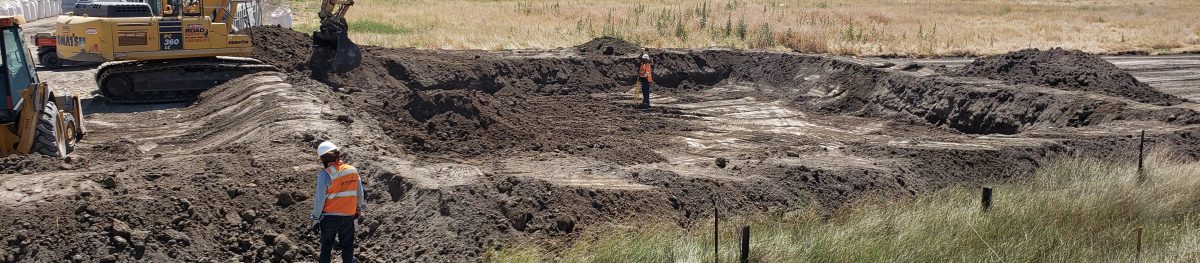
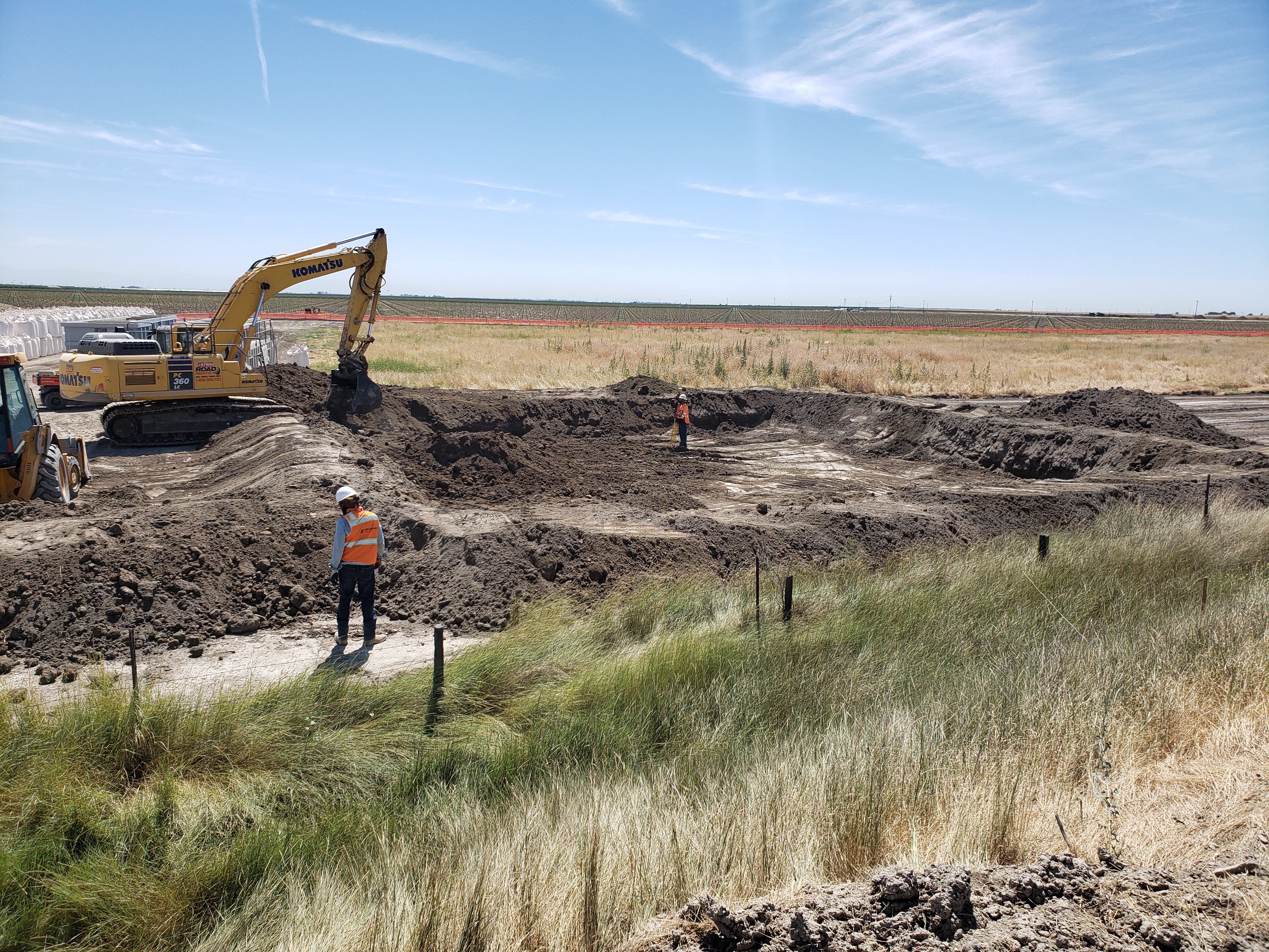
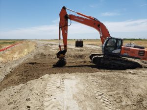
First, crews cleared the ground of vegetation and regrade portions of the levee in preparation for the culvert installations and slurry cut-off wall. The images below show the start of clearing and grubbing the waterside at the southern end of the project. The orange fencing is wildlife exclusion fencing that surrounds the entire project site. A drill rig is on the levee crown to obtain additional information about the soils to complete the design mixture for the cutoff wall.
![]()
Construction crews then prepped the levee and installed concrete-reinforced culverts to replace aged corrugated metal culverts.
After replacing the culverts, crews backfilled the trenches and buried the new culverts.
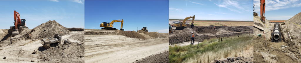
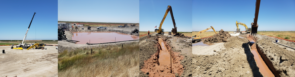
Crews then trenched and poured slurry walls to re-enforce existing levees. In the first photo below, a long-reach arm is being installed on the slurry wall trench excavator. The second photo show the bentonite slurry pond which will serve as the source of slurry for filling the slurry wall. The third photo shows the main slurry wall trench excavator dumping a bucket of removed levee material while slurry is continuously pumped in. And, the final photo shows supporting operation blending backfill to be placed back in the trench.
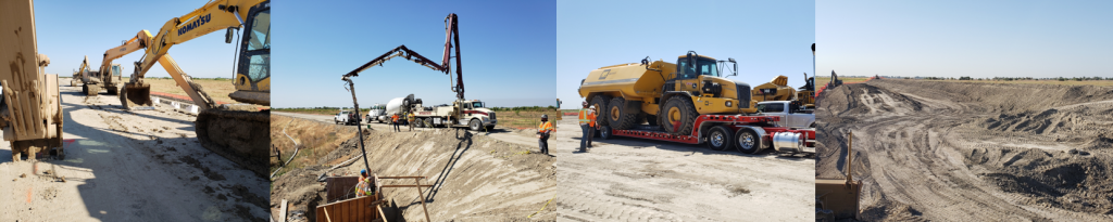
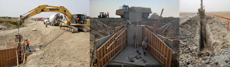
Phase 2 includes installing a slurry wall in about 1,500 feet of levee (Reach O-1). It also includes replacing two 24” corrugated metal drainage pipes with reinforced concrete pipes and replacing a 36” corrugated metal irrigation diversion pipe with a reinforced concrete pipe. Replacement of the irrigation pipe includes constructing a bypass pipe so irrigation deliveries can continue. Photos below, left to right, show excavators parking along the slurry wall working platform after a long day; pumping concrete into the head wall form of a culvert inlet structure; arrival of the K800 (8,000 gallon water truck); and, earthwork progressing into Phase 2.
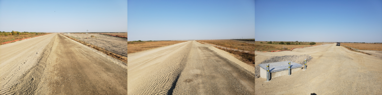
Final photos of the project completed with levee regraded.
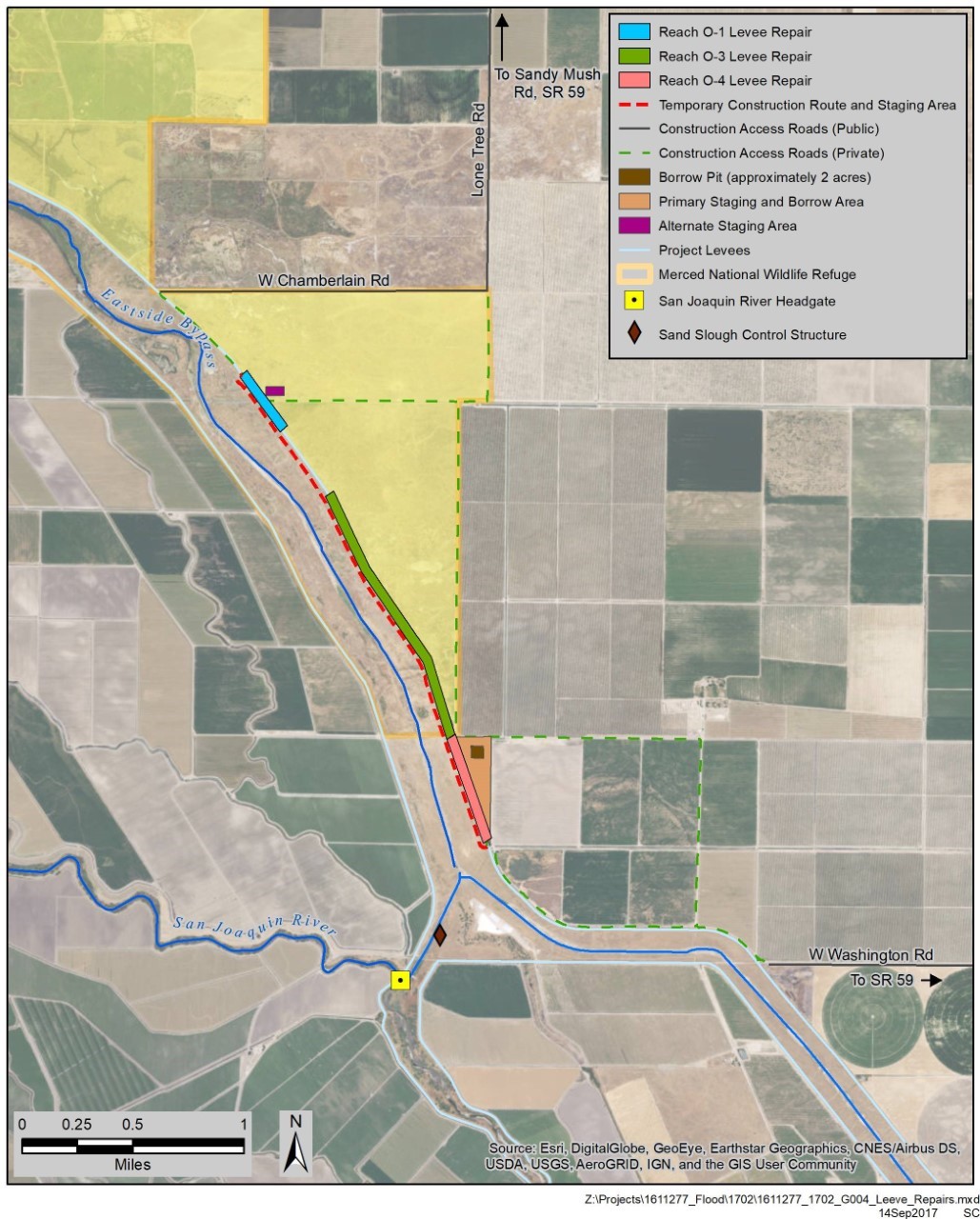
A link to the full project field advisory is here. Below is a map showing the construction area.